Machine-to-machine communication for automated synthesis of organic coating materials using HTTP and OPC-UA protocols
with OPC-UA Historical Data Access support using .NET OPC UA SDK


Introduction
As the world and industry have started to rely more on batteries to address the global energy challenge and get away from fossil-fuel use, more innovation and research is needed. The Battery Interface Genome – Materials Acceleration Platform (BIG-MAP) is the European project which aims to speed-up the battery innovation and materials discovery by providing “technological and scientific building blocks” across the full batter value chain: discovery, simulation, characterizaiton and autonomous synthesis. To read more about the BIG-MAP project and the long-term European research initiative Battery 2030+, please, consider https://www.big-map.eu and https://battery2030.eu websites.
Being part of the BIG-MAP project and working on the robotic synthesis of electrode coating materials, in this article we want to describe the software prototype system that enables machine-to-machine communication between system components. The system would allow robotic synthesis of organic materials and, in general, consists of a central unit with a robotic arm and subsystems placed on trolleys around the central unit that can be arranged in any layout.
For subsystems in the BIG-MAP project, we’re aiming to cover the following processes:
- Mixing with a magnetic stirrer subsystem
- Separation of compounds with a rotary evaporator
- Sampling and testing with pressurized flasks and valves
- Extraction with a liquid-liquid extractor
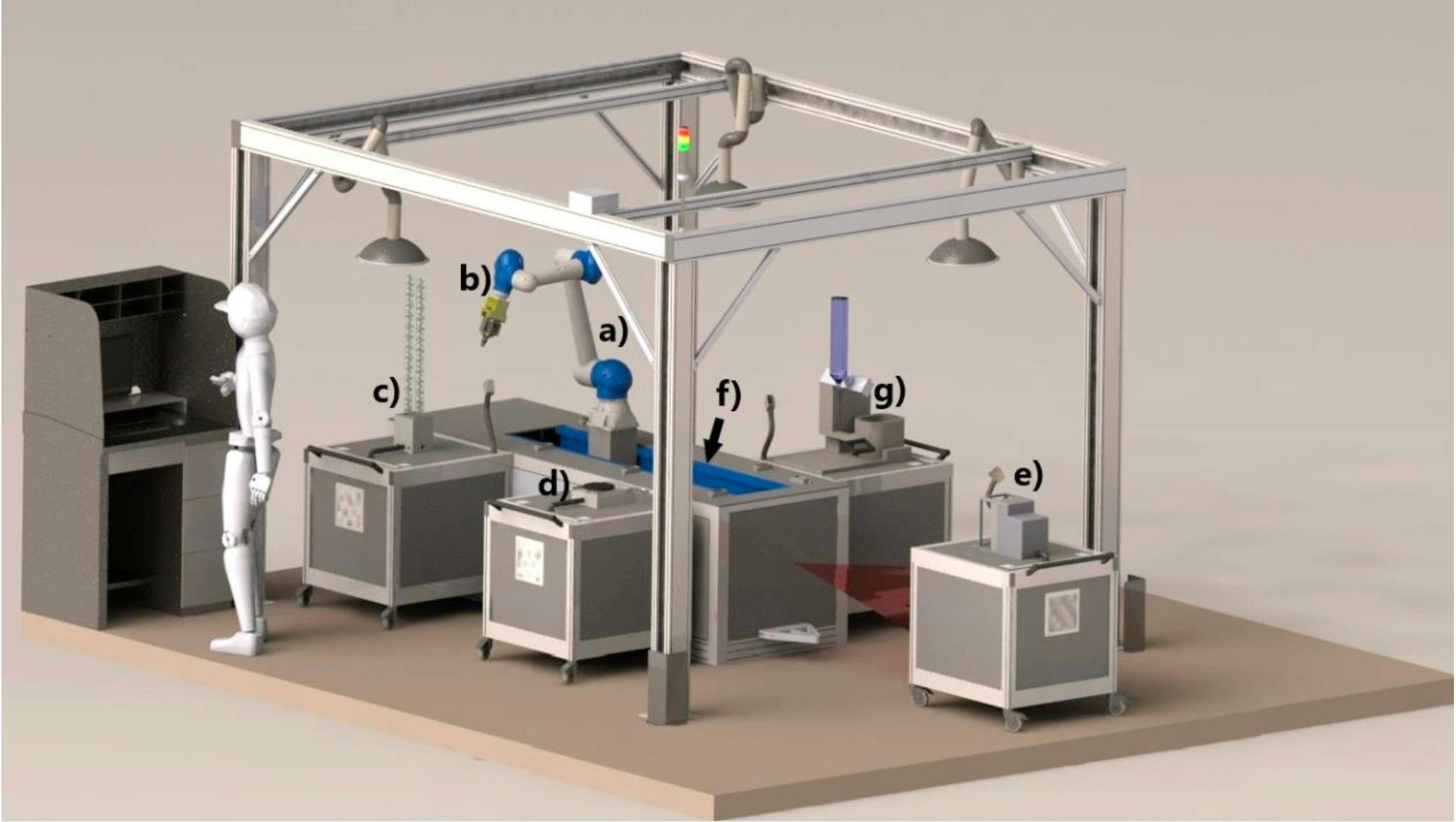
For this article, we take the liquid-liquid extraction (LLE) system and mostly the software that enables communication between system components. LLE separates two different liquids that formed a distinct liquid-liquid interface. The draining part of the device has a rotary valve and a light sensor that reads light wavelengths which are used for the liquid-liquid interface detection by an ad hoc algorithm. A user can choose what liquid to separate, the liquid that in the upper part or lower part of the vessel.
The LLE device exposes HTTP API to control the hardware. The input request for the device includes:
- What part of liquid is needed: upper or lower
- How much of the liquid is needed in milliliters
- Device settings: speed of the rotary valve, light sensor sensitivity, etc.
Downstream systems can take the device settings and optimize values for them using ML techniques to get the best separation of the liquids.
One of the goals of this article, besides presenting the design and implementation of the software that enables communication between components, is to showcase a use for the Historical Data Access feature of OPC-UA protocol that is specified in Part 11 of the OPC UA Reference.
Design
The LLE system consists of multiple devices and subsystems: a camera, draining system, belt, light sensor system, and interface detection software. This article focuses on the belt and light sensor (BLS) system. The rest of the components can be implemented similarly.
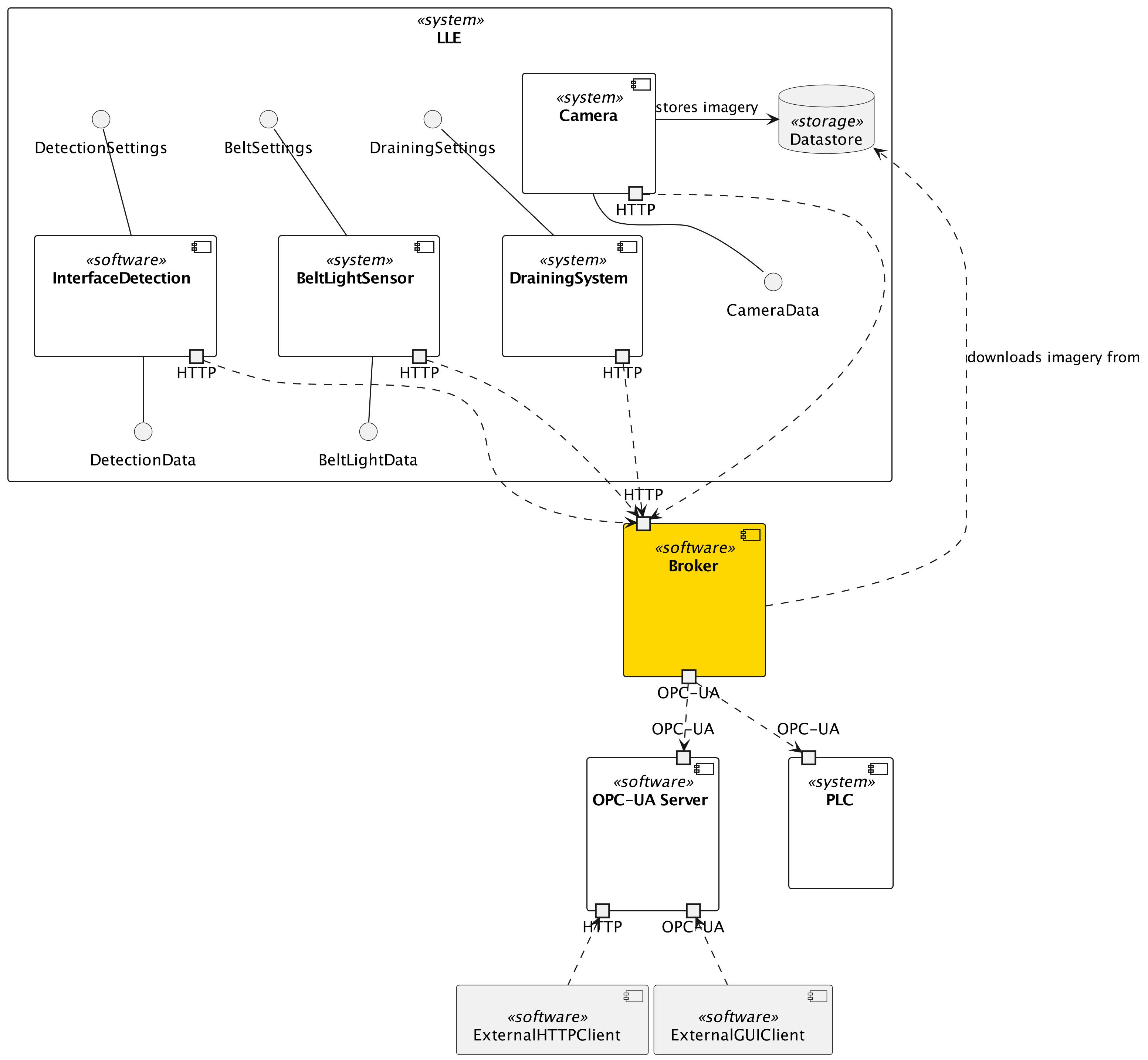
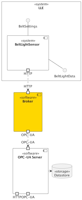
The simplified architecture is the following:
Components
The system consists of the LLE component (BLS), the intermediate component (Broker) and any other downstream consumer of the intermediate component’s API, e.g., OPC-UA server on PLC or a standalone server which in its turn distributes the data to its consumers.
BLS component is a device with LEDs and a light sensor that go along a flask with two liquids in it, it shoots a light beam through the flask and the sensor measures wavelengths it detects. This data is used later together with photographs from a camera from another component to detect the liquid-liquid interface.
Broker is an intermediate component that relays information between all the connected systems. It has all the necessary clients to utilize HTTP, OPC-UA or any other protocol to exchange data. It can be programmed to do it periodically, on schedule or on an event.
On the other side of the broker is OPC-UA Server. It is another component that publishes a signal to start an experiment and, then, collects all the data while the experiment is running. This component can be a PLC’s OPC-UA server or a standalone one.
Communication
In general, communication between OPC-UA Server and BLS is organized via Broker. OPC-UA Server publishes a signal to initiate the liquid extraction procedure; Broker catches the signal and relays it to BLS. BLS exposes measurements through its HTTP API, which is polled periodically by Broker to deliver results back to OPC-UA Server. Broker has an HTTP client to communicate with BLS and OPC-UA client for OPC-UA Server.
Why do we use Broker and do not connect directly to OPC-UA Server? In a simple case, we do not want an additional system like Broker to be in the middle of the communication as it introduces an additional delay and increases the overall complexity. However, when we have multiple systems and, in some cases, an even unpredictable amount of components that can be plugged into the communication, it might be helpful to introduce an intermediary. Only the intermediary would have direct access to the PLC’s OPC-UA server, and only in the intermediary would we need to implement an OPC-UA client. All the other components would need to expose their APIs in whatever way they can, and they are unaware of how those APIs would be used. This simplifies the development of components’ APIs and unifies communication across the network.
Historical Data
In the current architecture, we have one piece of data worth storing, and it is labeled as “BeltLightData” on the diagram. It consists of wavelengths measured by the light sensor in the BLS component. As this data is used later for the liquid-liquid interface detection, we need to store everything we get from BLS for further usage.
In real settings, we would probably introduce a couple of layers to the current architecture, such as operational and analytical levels, to group all the components according to the data lifetime and reaction time. We do not need to do that here, so we store the historical data on OPC-UA Server’s side.
OPC-UA Server Information Model
To build the OPC-UA server, we need to have an information model of the systems we want to connect to the server. For that purpose, instead of OPC-UA-specific modeling notation, we used a bit more widely used UML because of familiarity and the PlantUML tool available to generate model images.
In the figure below, we have LLE as a root folder for the device. Inside LLE, there is the belt-light-sensor object that contains the following entities:
- IsStarted: DataVariable with the underlying type bool
- ResultsInput: DataVariable with string
- Results: DataVariable with [][]int
- Settings: object
- NumOfLEDs: DataVariable with uint16
- DeltaLEDs: DataVariable with uint16
- TravelDistance: DataVariable with uint16
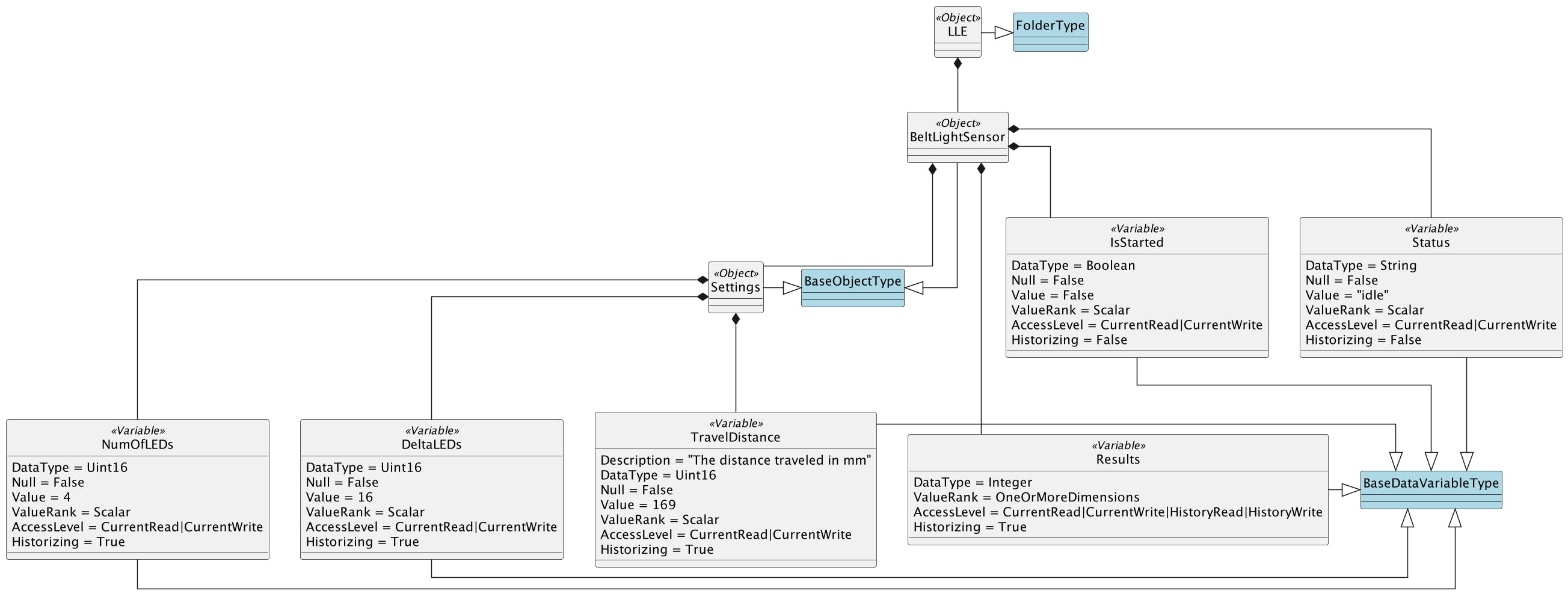
When the IsStarted variable is set to True, the experiment has started, and all the downstream systems that listen to this variable must start their work. One may notice that we have one similar variable with different data types, ResultsInput: string and Results: [][]int. The reason for this is that the implementation of Broker, which is described below, cannot write n-dimensional arrays to the OPC-UA server where n > 1. For that reason, we serialize the array to a string, write it to ResultsInput as a string, and the server then parses it to the proper datatype and writes it to the Results variable. We had to do this workaround to keep the intermediate broker without significant changes.
Results stores wavelengths of the light sensor which is the essential data for the liquid-liquid interface detection algorithm.
Further, we have the Settings object that allows setting some settings for the belt-light-sensor system if we want to change the defaults.
BeltLightSensor (BLS) HTTP API
For the purpose of this article, we would not use the real HTTP server of BLS because we cannot run it without the actual device attached. So, we developed a mock version of BLS HTTP API that has very similar endpoints with almost the same datastructures used.
The full API scpecification in OpenAPI JSON format is the following:
{"openapi":"3.0.2","info":{"title":"FastAPI","version":"0.1.0"},"paths":{"/":{"get":{"summary":"Get Root","operationId":"get_root__get","responses":{"200":{"description":"Successful Response","content":{"application/json":{"schema":{}}}}}}},"/start":{"get":{"summary":"Do Start","operationId":"do_start_start_get","responses":{"200":{"description":"Successful Response","content":{"application/json":{"schema":{}}}}}},"post":{"summary":"Post Start","operationId":"post_start_start_post","requestBody":{"content":{"application/json":{"schema":{"$ref":"#/components/schemas/Settings"}}},"required":true},"responses":{"200":{"description":"Successful Response","content":{"application/json":{"schema":{}}}},"422":{"description":"Validation Error","content":{"application/json":{"schema":{"$ref":"#/components/schemas/HTTPValidationError"}}}}}}},"/status":{"get":{"summary":"Get Status","operationId":"get_status_status_get","responses":{"200":{"description":"Successful Response","content":{"application/json":{"schema":{}}}}}}},"/stop":{"get":{"summary":"Do Stop","operationId":"do_stop_stop_get","responses":{"200":{"description":"Successful Response","content":{"application/json":{"schema":{}}}}}}},"/results":{"get":{"summary":"Get Results","operationId":"get_results_results_get","responses":{"200":{"description":"Successful Response","content":{"application/json":{"schema":{}}}}}}}},"components":{"schemas":{"HTTPValidationError":{"title":"HTTPValidationError","type":"object","properties":{"detail":{"title":"Detail","type":"array","items":{"$ref":"#/components/schemas/ValidationError"}}}},"Settings":{"title":"Settings","type":"object","properties":{"sleep_delay":{"title":"Sleep Delay","type":"integer","default":15}}},"ValidationError":{"title":"ValidationError","required":["loc","msg","type"],"type":"object","properties":{"loc":{"title":"Location","type":"array","items":{"anyOf":[{"type":"string"},{"type":"integer"}]}},"msg":{"title":"Message","type":"string"},"type":{"title":"Error Type","type":"string"}}}}}}
To view it in a human-readable form, we can paste the JSON document above into the Swagger Editor available at https://editor.swagger.io. It will convert JSON to YAML and will display the endpoints with request and response attributes that are easily readable. As a table, the endpoint's documentation would look like this:
| Verb | URL | Parameters | Request Body | Response | Description |
| GET | /start | {"status": string, "settings":{"sleep_delay": integer},"results": [][]integer} | Starts the experiment | ||
| POST | /start | {"sleep_delay": integer} | {"status": string, "settings":{"sleep_delay": integer},"results": [][]integer} | Starts the experiment. “sleep_delay” imitates some work being done on the server for this amount of seconds | |
| GET | /status | {"status": string, "settings":{"sleep_delay": integer},"results": [][]integer} | Returns the current status of the server altogether with settings and results if available | ||
| GET | /stop | {"status": string, "settings":{"sleep_delay": integer},"results": [][]integer} | Stops the experiment and removes all the temporary data | ||
| GET | /results | {"status": string, "settings":{"sleep_delay": integer},"results": [][]integer} | Returns the results of the experiment |
For the server status, we have the following enumeration:
- idle
- running
- finished
- stopped
Broker
As was mentioned above, the primary purpose of the broker is to relay information and organize the communication between components of the whole system. Broker has a scheduler that polls the OPC-UA Server and BLS HTTP API periodically to react to changes in either of them. So, the main components of Broker are the scheduler or a task management system and different clients that connect to subsystems. What clients are there depends on what protocols are used. In our case, it is HTTP and OPC-UA.
Implementation
BLS Mock-Up HTTP API
The implementation of the mock-up HTTP API is available at GitHub, github.com/BIG-MAP/WP4-BLS-MockUp. It is written in Python using the FastAPI web framework and the pydantic library to simplify the serialization of a server's response.
The implementation follows the specification described in the previous section. From the implementation details, the worth mentioning part might be how we implemented an immediate response from the server instead of waiting for a main working routine to finish.
Python has asyncio standard library that provides the high-level API for concurrent programming. To return from the /start controller immediately, we create an asynchronous task and submit it to a running event loop on the current thread. This also gives us a task handle if we want to cancel the job prematurely. If it is impossible to use an asynchronous routine, we need to create a task and submit it to a separate thread, so it would not block the current thread where the server is running.
Node-RED as Broker
To implement Broker, we chose Node-RED, which is an excellent prototyping tool. It also has the node-red-contrib-opcua OPC-UA plugin that allows us to browse, read and write OPC-UA nodes. HTTP client is available as a built-in tool. This gives everything that is needed to implement the information polling and exchange workflows. The source code for this component is available at GitHub, github.com/BIG-MAP/WP4-NodeRED-Broker.
As Node-RED uses a workflow as a basic deployable unit, how Node-RED Broker is implemented is better represented by the two workflows below.
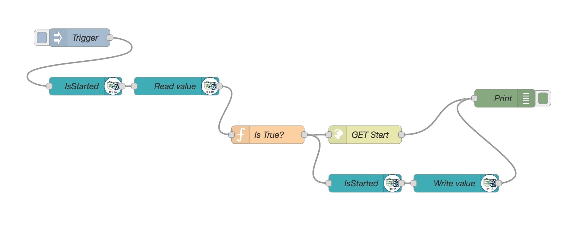
Workflow 1 represents a logic for querying the IsStarted variable on OPC-UA Server. As soon as the variable is set to True, the BLS HTTP /start endpoint is called to initiate the experiment.
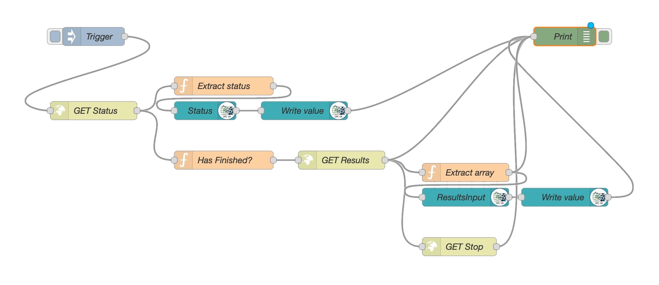
Workflow 2 implements polling the status of BLS server and updating the corresponding BLS status on OPC-UA Server. Also, the workflow fetches the results (wavelengths from the light sensor) when they are available and writes them to the OPC-UA ResultsInput node.
Here some explanation is needed to understand why we do not write straight to the Results node on OPC-UA Server. The reason for this is that the Node-RED OPC-UA plugin does not allow to write n-dimensional arrays (with n > 1) to OPC-UA nodes. The Results datatype on the OPC-UA’s side is [][]int, but we cannot use it immediately. So, we introduced another node on OPC-UA, ResultsInput, with the string type. On Node-RED, we serialize the array to a string separated by commas and semicolons. On the OPC-UA’s side, we deserialize it to an array and update the correct Results node to the most recent proper state.
During the testing, we also noticed that the node-red-contrib-opcua plugin often fails. One of the exceptions was an error in certificates for OPC-UA, even though we used an anonymous unsecured connection. In real settings, we must either fix the failures or change Node-RED with a more reliable implementation of the Broker component.
OPC-UA Server using .NET SDK
For the OPC-UA server implementation, we used the .NET reference implementation of OPC-UA, which seems most frequently updated on the internet and publicly available. This implementation has two licenses, RCL for OPC Foundation members and GPL 2.0 for the rest. GPL 2.0 requires users, besides everything else, to publish their source code. The source code for the OPC-UA server implemented for this article is available at GitHub, github.com/BIG-MAP/WP4-OPCUA-Server. The SDK is available as a NuGet, OPCFoundation.NetStandard.Opc.UA v.1.4.370.12.
OPC UA Online Reference is the primary source of knowledge about the OPC-UA protocol. It describes all the concepts, nodes, attributes, and services in detail. However, mapping these concepts to the actual .NET implementation is not straightforward. That is why applications from the .NET OPC-UA SDK and samples were the best documentation source during this work. Hopefully, this article will give one more sample application to the community to learn and improve.
Tooling
Before describing the implementation, it would be helpful to introduce some tools that helped develop the OPC-UA server.
We used FreeOpcUa Modeler written in Python and UaModeler from Unified Automation for modeling. FreeOpcUA Modeler failed to produce XML files that could have been used directly to import into the OPC-UA server, but it runs across more platforms (Windows, Linux, macOS). UaModeler runs on Windows and Linux, UI in some places is distorted, and it can be difficult to read some labels, but it works. We used UaModeler to generate the necessary node set for the server. However, keep in mind that in the trial mode, it allows exporting only up to ten nodes. It is also possible to avoid modeling tools and compose nodes with code.
For accessing and browsing OPC-UA servers, there are several options available. FreeOpcUa Client can be a good option; in our case, it did not work all the time as expected, and it does not have historical data querying support. Unified Automation has UaExpert, which works as expected, but there is a nicer option from Prosys OPC called Prosys OPC UA Browser. On macOS, it can be installed with Homebrew, brew install --cask prosys-opc-ua-browser. It has a friendlier UI and sample simulation server provided by Prosys to compare one's implementation with theirs, which might be helpful for some debugging.
Implementation
OPC-UA Server consists of the main Program class that instantiates Opc.Ua.Configuration.ApplicationInstance class with our custom configuration provided by the Configuration class. Program also creates a Server object, which contains the main logic for the server.
Server inherits from the standard server implementation provided by .NET OPC UA SDK and provides the following custom functionality:
- Address Space consists of the imported node set generated with UaModeler
- Modifications to the services provided by this server: Write and HistoryReadRawModified
- Datastore is an API for the data storage needed to provide the Historical Data Access (HDA) OPC-UA feature
The Datastore API, in this case, is a class that uses the file system as a storage device and serializes wavelength results from the light sensor to a text file and reads it back from it. It can be replaced with a database connection without changing the dependent components, but only by modifying the internal implementations of serialization and deserialization functions.
Write service has been modified to resolve the issue with the Node-RED OPC UA plugin described in the previous section. The plugin could not write n-dimensional arrays where n > 1. So, the ResultInput node was introduced at the OPC-UA server with the string datatype. In the Write **service, we check for any modifications to ResultsInput, deserialize string into an n-dimensional array and insert the record into the datastore, i.e., into our history. There is a better place to receive history updates, the HistoryUpdate service, but the Node-RED OPC-UA plugin does not support this either.
HistoryReadRawModified service provides the main logic for HDA. In our prototype, only one node supports history, so all the code related to that one node is placed right into the service. In the service, we check for the node's name and extract request attributes such as start and end times for the historical time range. We also take into consideration the maximum amount of values each node returns. If the amount of data is more than requested, a continuation point is created and saved in the saver, so the request may continue later from the same point where it stopped processing.
Conclusion
This article presents the proof-of-concept design and implementation of software components for the liquid-liquid extraction system that communicates with the OPC-UA server (PLC in real settings) across the network through the intermediary that relays and queues all the communication between the components.
The implementation uses three programming languages, Python, JavaScript, and C#, because the tools used come from different vendors. In theory, unifying all the components and using only one language is possible. However, Python is often a de-facto language in academia, so it will be used as far as the necessary libraries are available. There is a Python implementation of the OPC-UA protocol, but it is not certified and does not support the full OPC-UA specification. So, the .NET OPC UA stack seems more reliable for industrial use.
Broker implementation using Node-RED was enough to pass the testing, but we observed many crashes caused by the Node-RED OPC-UA plugin. In the future, it is worth considering contributing to the plugin to resolve the issues or changing the implementation with a custom Python script or an off-the-shelf message broker.
BLS HTTP API implementation using the FastAPI web framework did not cause any unexpected problems and has worked well. FastAPI also automatically generates an OpenAPI specification for its endpoints, simplifying collaboration between team members.
For the future, after replacing the most unreliable Node-RED Broker implementation, it is worth continuing to extend this prototype and conduct a workload test to see how the system behaves under stress. Because in real settings, it is expected to have many more devices, the rate of requests would be several orders of magnitude bigger. The current OPC-UA server implementation also exposes BLS settings but does not provide support for it. The BLS system has default settings that worked quite well, i.e., it can detect a liquid-liquid interface, but it is still worth implementing the support for changing the number of LEDs and the travel distance of the device.
Bibliography
[1] W. Pessemier, G. Raskin, H. Van Winckel, G. Deconinck, and P. Saey, “A practical approach to ontology-enabled control systems for astronomical instrumentation.” arXiv, Oct. 21, 2013. Accessed: Sep. 13, 2022. [Online]. Available: arxiv.org/abs/1310.5488
[2] A. Korodi and I. Silea, “Achieving interoperability using low-cost middleware OPC UA wrapping structure. Case study in the water industry,” in 2017 IEEE 15th International Conference on Industrial Informatics (INDIN), Emden, Jul. 2017, pp. 1223–1228. doi: 10.1109/INDIN.2017.8104949.
[3] G. A. Topalian-Rivas, J. Wassermann, M. Severengiz, and J. Kruger, “Automated dashboard generation for machine tools with OPC UA compatible sensors,” in 2020 25th IEEE International Conference on Emerging Technologies and Factory Automation (ETFA), Vienna, Austria, Sep. 2020, pp. 1009–1012. doi: 10.1109/ETFA46521.2020.9212136.
[4] H. Eichelberger et al., “Developing an AI-enabled IIoT platform -- Lessons learned from early use case validation.” arXiv, Jul. 10, 2022. Accessed: Sep. 13, 2022. [Online]. Available: arxiv.org/abs/2207.04515
[5] S. Malhao, R. Dionisio, and P. Torres, “Industrial IoT Smartbox for the Shop Floor,” in 2019 5th Experiment International Conference (exp.at’19), Funchal (Madeira Island), Portugal, Jun. 2019, pp. 258–259. doi: 10.1109/EXPAT.2019.8876562.
[6] A. Nicolae and A. Korodi, “Node-Red and OPC UA Based Lightweight and Low-Cost Historian with Application in the Water Industry,” in 2018 IEEE 16th International Conference on Industrial Informatics (INDIN), Porto, Jul. 2018, pp. 1012–1017. doi: 10.1109/INDIN.2018.8471928.
[7] W. Mahnke, S.-H. Leitner, and M. Damm, OPC Unified Architecture. Berlin, Heidelberg: Springer Berlin Heidelberg, 2009. doi: 10.1007/978-3-540-68899-0.
[8] F. Pauker, S. Wolny, S. M. Fallah, and M. Wimmer, “UML2OPC-UATransforming UML Class Diagrams to OPC UA Information Models,” Procedia CIRP, vol. 67, pp. 128–133, 2018, doi: 10.1016/j.procir.2017.12.188.
[9] S. Wrede, O. Beyer, C. Dreyer, M. Wojtynek, and J. Steil, “Vertical Integration and Service Orchestration for Modular Production Systems Using Business Process Models,” Procedia Technology, vol. 26, pp. 259–266, 2016, doi: 10.1016/j.protcy.2016.08.035.
Acknowledgements
I want to thank Rodrigo Moreno and Shahbaz Tareq Bandesha. They played an active role in testing the prototype's implementation and provided valuable advice regarding the liquid-liquid extraction system and PLC programming.
This project has received funding from the European Union’s Horizon 2020 research and innovation programme under grant agreement No 957189.